Home / Articles / How Do I Calculate Feet of Head for My Pool?

How Do I Calculate Feet of Head for My Pool?

How to calculate head for pool pump?

OK, riddle me this, you’re standing in a pool store’s showroom and you’re in awe of all the shiny new pumps. You finally make your decision on the model you want and have a hunch it will work well in your 20 000-gallon pool, but the salesperson drops a bomb on your plans by asking the simple question, “What is your feet of head?” Wait a minute, what? My head is about 10 inches. but I’ve never actually measured my own skull…

Wrong head.

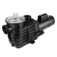
Total Dynamic Head (TDH) refers to the total equivalent height that a fluid will be pumped by taking into consideration any friction losses in the pipe. Essentially “dynamic head” is the measurement of resistance working against your pool pump as it pulls water from your basin and pushes it back to the pool. The total sum of the pipes’ lengths, rise in elevation and addition of 45-degree /90-degree turns will affect the feet of head number. All the aforementioned plumbing quirks add up to more friction the water accrues as it travels. The more friction, the harder the pump must work to push the water through the pipe, which demands that you go to a higher HP or use a larger pipe. If you need to install a new pump or replace your filter, you need to calculate the system’s feet of head to determine the best fit. A pump’s flow rate is dependent on the feet of head.

If you need to install a new pump or replace your filter, you need to calculate the system’s feet of head to determine the best fit. A pump’s flow rate is dependent on the feet of head of your plumbing system, and that measurement is featured in every pump curve chart. If you want to turn over your 20 000 gallons once in 5 hours, you will need to average at least 67 gallons per minute (GPM). We will use that GPM to calculate our pool’s feet of head.

Measure the Lengths of All the Pipes

Yes, I mean all. Measure the pipes’ lengths that span from your main drains, skimmers and any other suction ports that draw water from your pool. While measuring lengths, also note the depth of the pipe as well as the number of turns and the type (45-degree or 90-degree.) The type of turns will affect the friction loss as we total up at the end. Measure the lengths of the pressure side pipes in the same manner, noting the degree of turns and any valves you can see. The chart shows the feet of head per 100 feet of pipe according to the pipe diameter of Schedule 40 PVC in congruence with the flow rate of your pump. So, let us estimate you have 200 feet of 2” PVC with a flow rate of 70 GPM, your feet of head would be 15.2.

GPM1-1/2″ PVC2″ PVC
409.432.75
5014.34.16
60205.84
7028.67.76
8036.79.94

On top of that 15.2 feet of heads, you can add the rise in elevation from the pool’s surface to the pump. For example, if the pool’s pump is 3’ above your pool’s surface, add 3’  feet to 15.2.

Pipe section feet of head: 18.2

Because you know the gallons of your pool and you know that you want to turn over your water twice, you can calculate the desired rate of flow to turn it over in a period of 3-5 hours.

Add up the Dips, Turns, and Twists

We must now add in the effect of  all the valves, turns and couplings in  your plumbing line. Each of those plumbing add-ons tack on a value of feet of head to your plumbing line. The value will vary according to the flow rate you put in. I used 70 GPM as our flow rate in my calculations.

The table below provides the equivalent feet of straight pipe for representative connectors for 1 ½’ and 2’  at 70 GPM. The total of these values will have to be converted to feet of head as we will show in the example:

Description1-1/2″ PVC2″ PVC
45-Degree Elbow2.43.1
90-Degree Elbow7.68.7
Check Valve1.72.2
3-Way Diverter Valve2.52.3
2-Way Diverter Valve1.7
Tee6.27.5
Coupling1.52
CountDescription
5 x 8.7 = 43.5’90-Degree Elbows
4 x 2.0 = 8.0’Couplings
3 x 2.2 = 6.6’Check Valves
1 x 2.3 = 2.3’3-Way Diverter Valve
60.4 / 100 x 7.76 = 4.69 Total of 4.69 added feet of head for connectors.

Total of 60.4 added  equivalent feet of straight pipe.

To convert this value to feet of head, multiply 60.4 ‘ by the same number used in the length of pipe calculation above for 70 GPM and 2’ PVC diameter pipe, 7.76 per 100’ of pipe.

60.4 / 100 x 7.76 = 4.69

Total of 4.69 added feet of head for connectors.

Don’t Forget Your Filter, Valve or Heaters

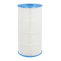
Filters can be a real drag on water as it rushes through your plumbing. So, we must account for that extra resistance. Pentair has a thorough Head Loss Chart that lists the ratings for their products. You may not have a Pentair, but the ratings should give you an idea of where your similar sized filter will fall on the chart. For your specific model’s head loss rating, check your owner’s manual or contact the manufacturer. Click the chart for an expanded view.

As for heaters, the head loss varies depending on flow rate and model. Here is a graph of Hayward listed flow rates to give you an idea, what the ranges may be. To be on the safe side I would add 15 feet of head to the count for a preliminary calculation, but for an actual number you will need to contact the manufacturer for calculations.

GPMFeet of Head
405.12
506.16
607.23
707.5
807.8
908.84
1009.86

The final total:

Pipe lengths and rise = 18.2
Valves and turns = 4.7
Cartridge filter 70 sq. ft. = 7.5
Heater = 7.5

Total feet of head = 37.9

author avatar
Matthew Simmons Technical Writer & Pool Product Expert
Swimming pool expert at InyoPools and host of Poolside Chat, brings over a decade of experience in the pool industry.

Related Videos

77 responses to “How Do I Calculate Feet of Head for My Pool?”

  1. KD Avatar

    How does vertical rise impact feet of head? Have a pool on the second floor, but the pump/filter is on the ground about 10′ below the bottom of the pool.

  2. Lou Avatar

    How the heck do you find out how much pipe and elbows you have if its buried in the ground?

    1. Matthew Simmons Avatar

      Well, you can guesstimate a number of turns based on the position of the pump equipment in relation to the drain points. As for the length of pipe and rise, should be figured out by measuring the distance of the main drains and skimmers to the equipment.

      Or you can reference a builder’s drawing.

  3. Brian Avatar

    How does this calculation change if the pump is below the waterline?

    In my case, my pool equipment is about 3 feet below the waterline. The pipes from the skimmer/return lines to the pump are about a foot lower than the equipment (making it 4 feet below the waterline).

    Thoughts?

  4. Andy Avatar

    Using 2.5″ pvc pipe and fittings
    90 DEGREE 10 10 100
    45 DEGREE 7 5 35
    PIPE LENGTH 331 331
    GATE VALVE 6 8 48
    514/100
    5.14
    FILTER 7.5
    HEATER 7.5
    20.14 TOTAL HEAD
    This seems very low. Please help!

  5. Phil Terry Avatar

    What if the water is pumped up to a solar heating panel on the roof of the house. So pool is 9 feet deep and solar panel is 20 feet up on roof. Pump to roof pipes are about 70′ along garden wall, 20′ up to roof and back.

    1. Tony Avatar

      I also have a solar panel in my garage attic close to 20 above pump, then the pool base of 9 feet, along with 75′ along our pool fence. No reply yet?

  6. Dan Avatar

    If I have two heaters, do you count the head for both heaters or only one?

      1. A Tired Old Mechanical Engineer Avatar

        Wrong. Nobody hooks up pool heaters in series. The second heater would overheat. The flow pressure drop calculation will have to account for the flow being divided between two parallel heaters, complicating this simple analysis, but hydraulic network calculations do it all the time. For a simple calculation like pool circuit pressure loss, it’s no big deal. Think about it. Two heaters in parallel, or any pressure drop inducing component, generate less pressure drop than one.

  7. Clintonkak Avatar

    Wow thanks for the info i’m going to use it for for my science fair project! p.s i love how you decorated your website:)

  8. Nader Avatar

    I’m not an expert but the calculations for the vertical rise and fittings seem incorrect.

    Per the following article, I believe the vertical rise would be calculated from lowest point drain PVC to pool pump subtracting water height: (1.5 feet PVC below drain + 2 feet from top of water to pump = 3.5 feet vertical rise)

    http://www.marchpump.com/blog/how-to-calculate-total-dynamic-head-for-industrial-pump/

    The friction loss for fitting is expressed in “equivalent feet of straight run pipe” for the same size pipe. In other words, take # of elbows and multiply by equivalent straight run length for 1 elbow then use the friction loss for straight pipe. Using the STA-RITE tables, 1 elbow for 2″ pipe would be equivalent to 9 feet of pipe length. So for 5 elbows that would be 5 * 9 = 45 feet. Using your table for straight 2″ pipe that would be 45/100 * 7.76 = 3.492 feet of head. If you do that for the rest of fitting I’m pretty sure you won’t get anywhere near 58.2 feet.

    Also, STA-RITE tables seem very high compared to:

    http://www.spearsmfg.com/IP-4/05%20Engineering%20and%20Design.pdf
    https://www.plumbingsupply.com/flowchart.html

    In these table, 1 elbow would be in the neighborhood of 6 equivalent feet of straight run pipe compared to 9 for STA-RITE.

    1. Wondering Avatar

      I too question the “dips, turns and twists” total. Matthew, shouldn’t we apply the ‘7.76 per 100 feet’ factor to this?
      58.2 x .0776 = 4.52 for a total of 43.7 instead of 97.4

      1. Andy Avatar

        Please help me as I try to calculate TDH. Every chart for 90 Degree elbow is different! I know I’m missing something. I’ve got 10- 2.5″-90 degree elbows. Using the chart, I calculate 10*10=100. Thats just elbows. I got 45’s and 330 LF of 2.5″ pipe!
        Thanks in advance.

        1. BR549 Avatar

          And what about using “Long Radius” elbows? Wouldn’t that have any effect in lowering the resistance for a 90 deg ell?

          1. Mike the Mechanical Engineer. Avatar

            Absolutely correct!
            In fact, one should ALWAYS use Long Radius elbows, rather than a single 90 deg or even two 45 deg elbows (must be separated by minimum 4*Diameter) .

            A Long Radius elbow is roughly 250% more efficient.
            For a 2″ pipe, here is the difference in “Equivalent length (in feet) of straight pipe”:
            Example:
            Long Radius elbow: 3.6 eq. feet
            (2) 45 deg elbow: 5.4 eq. feet (must be separated by minimum 8″)
            A 90 deg elbow: 8.4 eq. feet

            Thus, one could save close to 5 ft per connection, times say up to 20 connections in the entire system (including all the buried ones) could add up to say… 100 eqv. feet in savings, which in turn, could lower the total head.
            Thus one could (maybe, just maybe) move down to a lower hp pump, and save considerable energy over the life of a pool (say 30+ years).
            Even if you can’t move down in hp, you are still saving energy, by reducing the load on the pump motor.

            The downside is it takes more space (and good planning) to use the Long Radius elbows, and many people try to squeeze their pool plumbing (pump, filter, heater, valves) into the smallest space possible.
            (Meanwhile, any dummy can use a bunch of 90 deg elbows.)

            Also, keep in mind that the connectors, add up to anywhere from 5-10% of the entire head, depending on your pool size and design. So your actual energy savings, could be very small, maybe as small as only 1-5%. But even 1% (times 30-40 years), is still savings. Energy Efficiency is all about squeezing out 1% here, 2% there and getting all those small savings to add up to something substantial.

            The bottom line is that most pool contractors are lazy and don’t do it. After all, they don’t care about the efficiency of your pool system – you are paying the electric bill, not them.

            Even my own pool – built 24 years ago – has a ton of 90 deg elbows, since back then – no one really cared about energy efficiency. So in a few years, when I am ready to replace everything, and install a modern automated pool… I’ll dig up that whole area and re-plumb it all neatly to get rid of that spaghetti mess and make it a truly energy-efficient system.

            So if you are building a pool new, or re-plumbing an existing pool, one should take the extra effort, to plan out the plumbing, to be the most efficient and hopefully save a little money in the long run.

  9. Jeno Csakvary Avatar

    Hi, I have a question that bugs me.

    There is a table of data , to calculate the ” feet of head ” of my pool.

    GPM 1-1/2″ PVC 2″ PVC
    40 9.43 2.75
    50 14.3 4.16
    60 20 5.84
    70 28.6 7.76
    80 36.7 9.94

    if I know the GMP pump that I need to buy why all the calculations? I do not know what is the GMP of the pump that I need to buy – yet to calculate “feet of head ” I have to know. Otherwise I can not do the calculation. Am I missing something?
    Thank you for you advise, Jeno

    1. Matthew Simmons Avatar

      The gallons per minute (GPM) of a pump is determined in part by the feet of head. The output of a pump can vary by 40 or more GPM depending on the feet of head, and style of pump, The charts in the article are there to give you an idea how GPM is affected by the pipe size.

      See the example below of a WhisperFlo pump curve; the lines labeled by letters are horsepowers from .5 and up. You can figure out the approximate feet of head using the general guidelines provided in the article. Using that feet of head calculation, you can use the pump curve to figure out the horsepower needed to match the GPM.

      feet of head for a pentair whisperflo

  10. Bob Avatar

    In the “Dips and Turns” section, a number of 1.5 inch items have lower head than the 2.0 inch items, which seems very wrong.

    Also, it would be nice if you could point to the reference material for the standard items (pipes, ells, valves, and so on) so that one could compute things for different flow rates, etc.

    1. Matthew Simmons Avatar

      Bob,
      It has been awhile since I wrote this but, one of the sources I used was Sta-Rite’s Friction Loss Chart.

      In the chart, you can see that 1-1/2″ has lower friction loss than 2″.

      1. Shawn Avatar

        Great work Matthew, one of the best explanations I’ve seen for this subject. One quick note about the friction loss in fittings. There is a substantial difference with threaded vs. slip fittings. Here is a link to a chart I often use for my calculations.

        http://www.engineeringtoolbox.com/resistance-equivalent-length-d_192.html

        1. Matthew Simmons Avatar

          Thanks, Shawn. That page is a nice find, good info.

      2. Jack Smith Avatar

        The chart is for equivalent feet of straight pipe, not for head. The 58.2 feet for the valves gets added to the 200 feet of straight pipe. 2.58 x 7.76 = 20 ft of head.
        Also the lift is measured from the water surface elevation of the pool, so if the pool is 6′ deep the static lift would be 3′ in your example. The head losses for filter and heater seem reasonable.
        The TDH would then be 20+3+7.5+7.5 = 38 feet.
        (I’m an engineer and I do this for a living)

        1. Gerald Avatar

          Jack
          Thanks for the clarification as I was getting way too much head with the bends I had and it did not make sense. There are 13 bends that the previous owner installed that I can see in my system and that was giving me over 200 head but when I add it to the feet of pipe I am only around 38 feet of head.

        2. mjr Avatar

          yup, we r also engineers, do many very large pumps.
          his head is way out of line.
          i actually dont agree with the lift head, i feel using the skimer as the surface
          plus the lcation of the pump lift is plenty. might add a few ft head to calcs as safety

          1. A Tired Old Mechanical Engineer Avatar

            Wrong. There is no net elevation change, or lift, to be added to pool pump calculations. The only exception would be to lift to an open water feature or initially filling an elevated solar heater, neither of which are likely to matter. You calculate from free surface to free surface. All the elevation changes net out to zero in a hydraulically filled system.

      3. James Avatar

        name James from Kenya can you send me a pdf of making a swimming pool from the beginning to end

      4. Johnbull Avatar

        @Matthew can you send me a pdf break down calculation of how to measure 2″ PVC pipes and 2″ fittings? With illustration diagrams if possible of feet of head for a pool.
        Because..I want to get a pump that will fit in my(10×6)m with 1.5m deep and shallow depth of 1m.
        Thanks very much for your help

    2. Dan Avatar

      This is because of the surface area inside the pipes. a 2″ pipe has more surface area than the 1.5″ pipe, so naturally more friction is created, thus a higher head value. Although, the 2″ will allow for a higher flow rate, so that should also be taken into consideration when sizing your pipe, especially for new builds.

    3. Another "Engineer" Avatar

      Honest question: why are there so many “engineers” looking up how to calculate feet of head, if you already know the answer?

      And since it is so clear cut your method of calculating feet of head, why do you all keep disagreeing?

      1. tulipeone Avatar

        Ha, ha, ha,…..

      2. Enjin Ear Avatar

        Big thumbs up to you. When did “engineers” have time to read these articles, and when did engineering degrees stop requiring English and spelling?

    4. Dork Avatar

      The smaller ID pipe has less inside surface area and therefore less friction.

      1. A Tired Old Mechanical Engineer Avatar

        Wrong.

      2. Steve Avatar

        It has a higher friction relative to the volume of water in the pipe. As the pipe diameter increases the volume increases faster than the surface area.

    5. Mike the Mechanical Engineer. Avatar

      ANSWER TO: In the “Dips and Turns” section, a number of 1.5 inch items have lower head than the 2.0 inch items, which seems very wrong.
      YOU ARE RIGHT! THAT CHART IS WRONG!

      Speaking as a mechanical engineer, the FIRST RULE OF ENGINEERING:
      DO NOT MESS UP YOUR – UNITS OF MEASURE!!

      Another minor rule is: You can’t mix and match charts…
      If you are going to use a chart, you have to use the whole chart and only that one chart.

      If you look at MATTHEW SIMMONS’s numbers:
      Most do not match the Sta-Rite’s Friction Loss Chart – AT ALL!!

      THE REAL ANSWER: USE THE STA-RITE CHART
      =========================================================================
      The real reason that the numbers for the “DIPS AND TURNS” look funny is because:
      a. It is WRONG!!
      b. You have to realize that the two charts (“Straight” vs “Turns”) use 2 fundamentally different units of measurement.
      – Straight piping is measured in “Loss of HEAD” (measured in head-feet)
      – “Dips and Turns” is measured in “FEET” (measured in feet)
      c. Since you have different units of measurement, you have to convert units.

      For example, for the STANDARD TEE, in Plastic:
      1.5″ = 13 ft
      2.0″ = 17 ft
      Looks funny right? That’s because we have to convert!

      Converting to “LOSS OF HEAD” (at 70 gal/min), we get the following:
      1.5″ = 13 ft * 28.70 head-ft / 100 ft = 3.70 head-ft
      2.0″ = 17 ft * 8.53 head-ft / 100 ft = 1.45 head-ft

      Thus, you can now see that the HEAD LOSS of a 1.5″ Tee is more than double that of a 2.0″ Tee.

      Therefore, the lesson learned is:
      a. One must use the same chart for all calculations
      b. One must use the chart properly, by realizing where different units are applied.

      I realize this is a lot of math for the non-engineer.
      However, if you go can through the MATTHEW SIMMONS’s original example, and fix all the values, using the STA-RITE chart, you will gain the experience needed to calculate your own pool.

      PS I typed this quickly, on the fly. So if I made an error, so be it.
      That’s why if I were doing this for real, I would sit down and check/recheck/recheck all my values and calculations.
      In fact, That is my SECOND RULE OF ENGINEERING:
      Check and Recheck, then Recheck again!

Leave a Reply

Your email address will not be published. Required fields are marked *